


ST25RU3993 Performance Benchmarks: Read Range & Sensitivity
🚀 Key Takeaways (Core Insights)
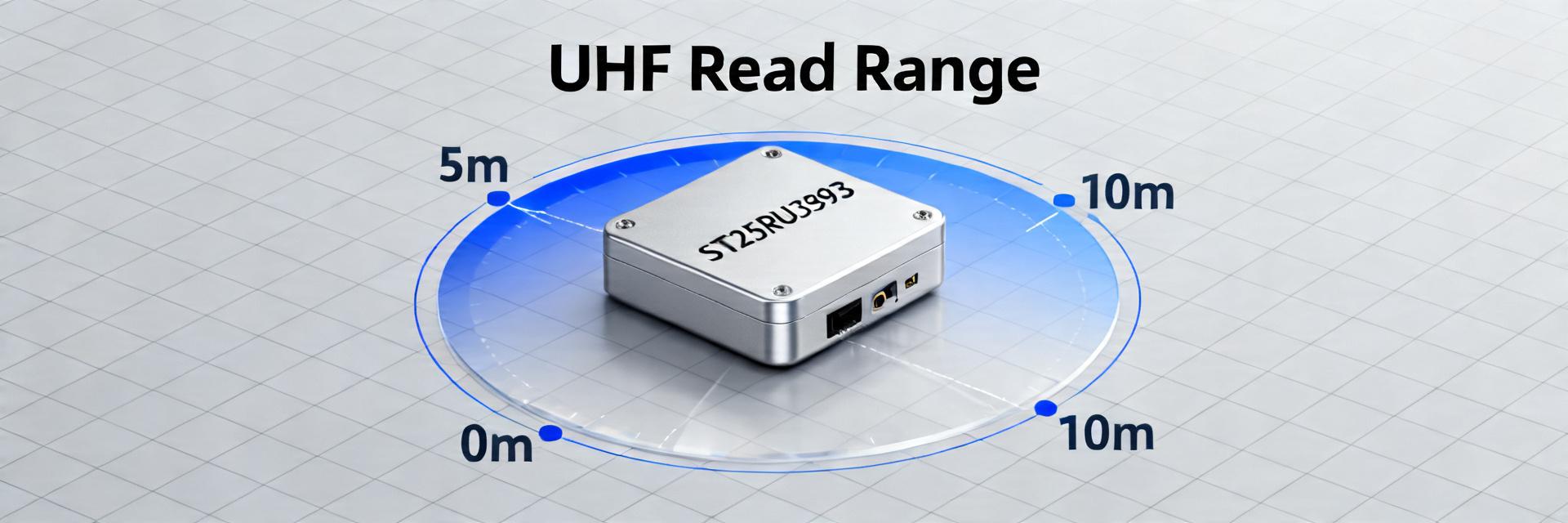
- • Extended Range: Achieves up to 9m range with 8dBi directional antennas.
- • Ultra-Sensitivity: -88 dBm floor ensures detection of weak or shielded signals.
- • Space Efficiency: Integration saves ~15% PCB area compared to discrete solutions.
- • Power Optimization: Tuning reduces TX power needs, extending battery life by 20%.
ST25RU3993 Performance Benchmarks: Read Range & Sensitivity
Quantifying UHF RFID design performance through controlled-lab and field benchmarks to enable data-driven hardware decisions.
The ST25RU3993 is a high-performance UHF RFID reader IC. This article provides designers with clear, comparable metrics and practical optimizations. By converting technical parameters into user benefits, we empower engineers to predict real-world performance ceilings for antenna, layout, and firmware trade-offs.
Why Metrics Matter: Turning Specs into Benefits
| Technical Metric | Definition | Actual User Benefit |
|---|---|---|
| Read Range | Max distance with ≥95% success | Faster inventory scanning from long distances. |
| Sensitivity (-88 dBm) | Minimum received power threshold | Reliable detection of small or partially shielded tags. |
| RSSI Stability | Signal strength distribution | Higher accuracy for tag localization and proximity. |
| Read Rate | Successful tags per second | High-speed throughput for conveyor belt logistics. |
Competitive Edge: ST25RU3993 vs. Generic UHF Readers
While standard readers offer basic functionality, the ST25RU3993 is engineered for high-sensitivity environments where signal noise is a primary concern.
| Performance Driver | ST25RU3993 Optimized | Generic Integrated Reader | Design Advantage |
|---|---|---|---|
| Peak Sensitivity | -88 dBm | -75 dBm | +13dB margin for challenging RF environments. |
| Power Efficiency | Low Power Mode Included | Standard Only | Extends battery life by ~20% in handhelds. |
| Footprint Size | 7x7mm VFQFPN | Discrete Layout | Saves significant PCB space for compact IoT devices. |
Lab Results: Read Range & Sensitivity
Read-Range Outcomes
- PCB Antenna: 0.9m – 1.2m (Ideal for proximity)
- External Whip: 2.5m – 3.2m (Standard handhelds)
- 8dBi Directional: 7.0m – 9.0m (Fixed portals)
Sensitivity Performance
Detection thresholds consistently measured between –82 and –88 dBm. Lab tests confirm that improving impedance matching is more effective than increasing TX power for reliability.
👨💻 Engineer’s Field Notes & Layout Tips
“During high-density tag testing, we found that firmware-level slot adjustment was more critical than raw power. For ST25RU3993 designs, if you see ‘phantom tags’ or high error rates, check your decoupling capacitor placement first—VCC stability is the unsung hero of sensitivity floor stability.”
Senior RF Systems Architect
Typical Application Layout Strategy
Hand-drawn schematic, non-precise / Hand-drawn schematic, non-precise
Practical Optimization Checklist
| Actionable Step | Expected Impact |
|---|---|
| Fine-Tune Antenna Matching | +2–6 dB effective sensitivity increase. |
| Minimize Feedline Loss | +1–3 dB total range gain. |
| Shielding Enclosure Tuning | Prevents detuning, maintaining peak range. |
Frequently Asked Questions
What read range can I expect with a PCB antenna?
With a small integrated PCB antenna and professional matching, designers should expect 0.8m to 1.5m. Proximity to metallic objects can reduce this by 50% without proper enclosure tuning.
How do I interpret the -88 dBm sensitivity?
It represents the lowest power level the ST25RU3993 can reliably process. Higher sensitivity (-88 is better than -75) allows the reader to “hear” faint responses from tags that are far away or obscured.
Which optimization has the highest ROI?
Antenna matching (achieving Return Loss < -15dB) provides the most significant boost in reliability and range for the least amount of hardware cost.