


SMD Power Inductor Selection: Choosing ASPI-0630LR
A Professional Engineering Guide for Power-IC and PCB Designers
Engineers selecting an SMD power inductor often face inconsistent loss, thermal hotspots, and unexpected saturation in real-world converters. Evidence from board bring-up and field units shows these issues crop up when datasheet numbers are taken at face value. This guide promises a clear, step-by-step selection path using the ASPI-0630LR as the worked example for a 3A buck converter point-of-load, addressing spec tradeoffs, practical tests, PCB and thermal tips, and a final validation checklist.
TARGET Target Audience: Power-IC and PCB designers seeking practical, reproducible rules for selection and validation.
01
Why SMD Power Inductor Choice Matters (Background)
1.1 Key performance trade-offs
Point: Inductor selection balances stored energy, DC resistance (RDC), saturation current and package size.
Evidence: Higher inductance or larger cores increase energy storage but typically raise RDC and package volume.
Explanation: Choosing the wrong balance raises conduction loss (lower efficiency), increases ripple, and can push the core into saturation under transients—each outcome worsening EMI and thermal performance on the PCB.
1.2 Where ASPI-0630LR fits
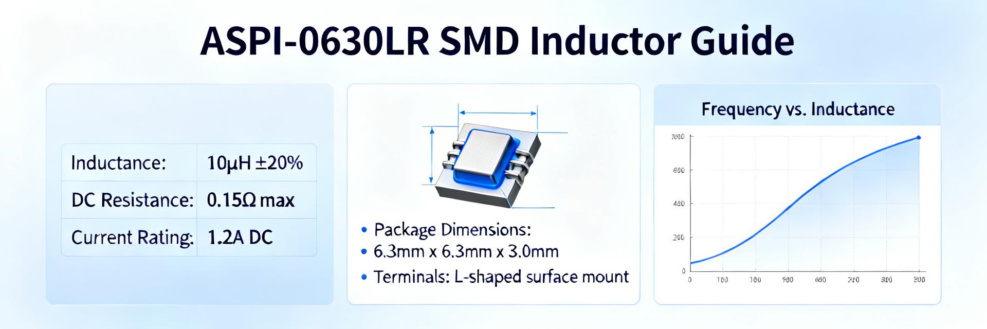
Point: The ASPI-0630LR is a compact molded power inductor intended for DC/DC converters where board space and reflow robustness matter.
Evidence: Typical current ratings cover the low-single-amp to multi-amp range with inductance choices suited to point-of-load buck converters.
Explanation: For 3A buck converters the ASPI-0630LR hits a sweet spot: small footprint, shielded construction, and variants that trade inductance versus RDC—making it a practical selection for moderate-frequency buck topologies.
02 Key Specs to Compare (Data Analysis)
2.1 Electrical specs that determine real-world behavior
Point: Inductance, RDC, Isat, Irms, SRF and temperature coefficient drive ripple, loss and margin. Evidence: Inductance sets ripple magnitude; RDC dictates I²R copper loss; Isat defines the current where inductance collapses. Explanation: RDC vs Isat must be weighed—lower RDC improves efficiency but may come with lower Isat or larger size.
Selection Trade-off Visualization: Performance Impact
Isat
RDC
Efficiency
Normalized impact of inductor core volume on key performance parameters
2.2 Interpreting datasheet test conditions
Point: Datasheet numbers are measured under specific frequency and temperature. Evidence: Lab Isat/Irms often need derating for ambient temp and DC bias. Explanation: Apply conservative margins—derate Isat by 10–30% for transient headroom. Consult ASPI-0630LR datasheet parameters for measurement conditions and adjust selection accordingly.
3 — Measured Performance
3.1 Practical loss & Saturation
Real loss is the sum of core and copper losses. For ASPI-0630LR expect copper loss to dominate at higher currents. Verify saturation behavior with step load tests to ensure the converter retains transient performance without core collapse.
4 — Selection Guide
4.1 Define Requirements
Rule-of-thumb: choose Isat ≥ 1.3× Ipk. Calculate required inductance from ΔI = Vin·D / (L·Fs). Map these to specific ASPI-0630LR part numbers based on switching frequency.
5 — PCB Layout, Thermal Management & EMI
Best Practices
Layout determines both losses seen and thermal dissipation. Short current loops and thick copper pours under the switching node reduce localized heating.
EMI Mitigation
Place the ASPI-0630LR close to the switching node and use low-ESL decoupling caps. Its shielded construction significantly reduces radiated emissions.
06 Application & Validation
Final Validation Checklist
- • Measure RDC and AC impedance at switching frequency.
- • Verify Isat curve against peak transient currents.
- • Thermal mapping: Ensure temperature rise is within limits.
- • EMI Scan: Check for radiated noise from the switching node.
- • Inspect solder joint integrity after reflow cycles.
Executive Summary
Choose an SMD power inductor by balancing inductance, RDC and Isat; ASPI-0630LR offers compact, shielded variants suitable for buck converters—verify using datasheet parameters and derating.
Measure both core and copper loss at your switching frequency and on a PCB mockup; validate thermal rise and transient behavior before production.
Follow layout best practices—short loops, thermal vias, and correct decoupling—to control losses and EMI when using ASPI-0630LR in point-of-load designs.
Frequently Asked Questions
How do I choose the right SMD power inductor value for a buck converter?
Pick L from delta-I = Vin·D / (L·Fs) to meet ripple targets; then ensure the chosen SMD power inductor variant has Isat ≥ 1.3× peak current and Irms rating after PCB thermal derating. Finally, confirm RDC is low enough to meet efficiency goals.
What tests should I run on an SMD power inductor before production?
Test RDC, AC impedance at switching frequency, Isat curve, and temperature rise on the actual PCB. Run transient load steps to observe saturation behavior and perform EMI scans. These tests verify that the SMD power inductor performs under real application conditions.
How do I prevent saturation and overheating with ASPI-0630LR selection?
Use conservative derating: select Isat ≥ 1.3× Ipk, verify Irms margin with expected PCB thermal resistance, and prefer a slightly larger core or lower RDC if temperature rise is high. Validate with thermal mapping on a populated board and adjust copper or vias as needed.