


GRT155R60J475ME13D datasheet: 0402 4.7uF specs & pad
GRT155R60J475ME13D Datasheet: Electrical Specs & Footprint
Introduction: The trend toward packing higher capacitance into 0402 MLCCs continues to change power-rail layout decisions, and a 4.7 µF X5R device in 0402 presents both opportunity and constraint. This article provides a data-led breakdown of GRT155R60J475ME13D electrical specs (from the official datasheet), practical PCB footprint recommendations, assembly and reliability considerations, and a concise design/procurement checklist. Readers will get a spec table, recommended land-pattern guidance, and measurable test checkpoints to accelerate validation.
This introduction references the term datasheet as the single authoritative source for numeric limits, curves, and mechanical drawings. Engineers should treat the tables and example plots below as implementation templates that must be confirmed against the official datasheet revision before final release to manufacturing.
(1) Product background & application context
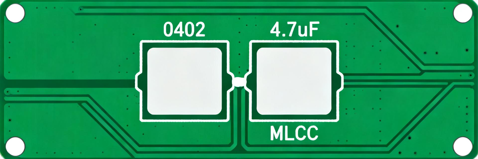
H3: Where this part fits (component class & typical uses)
Point: The part is an MLCC in 0402/1005 metric format intended for high-density decoupling and bulk bypass where board real estate is constrained. Evidence: 0402 MLCCs with 4.7 µF and X5R dielectric are commonly specified for low-voltage power rails. Explanation: In compact point-of-load and system-rail decoupling, a 4.7 µF 6.3 V X5R is chosen to suppress mid-band ripple while fitting tight placement envelopes; typical use-cases include decoupling for processors, power-management ICs, and small sensors operating at 1.2–5.0 V.
H3: Key electrical highlights at a glance
Point: Present a concise spec snapshot engineers can scan quickly. Evidence: The following table summarizes the typical characteristics engineers should validate against the official datasheet. Explanation: Treat the table as a quick-check; exact tolerance classes, temperature limits and any AEC-Q200 qualification must be verified directly in the datasheet before acceptance.
| Parameter | Typical/Example Value |
|---|---|
| Capacitance | 4.7 µF |
| Capacitance tolerance | ±5% (J) |
| Rated voltage | 6.3 V DC |
| Dielectric | X5R |
| Case size | 0402 / 1005 metric |
| Operating temp. range | typically −55 °C to +85 °C (verify datasheet) |
| AEC-Q200 | Check datasheet for qualification statement |
(2) GRT155R60J475ME13D — electrical specifications deep dive
H3: Capacitance behavior: DC bias & temperature characteristics
Point: High-capacitance MLCCs exhibit significant DC-bias and temperature-dependent capacitance reduction. Evidence: Datasheet DC-bias curves illustrate effective capacitance falling as applied voltage increases; X5R dielectric shows modest temperature-related drift within its rated range. Explanation: For a 4.7 µF X5R 6.3 V device, engineers should expect a multi-tens of percent reduction in usable capacitance at typical operating voltages (for example, at 3.3 V and 6.3 V). Recreate the datasheet DC-bias curve in your simulation and BOM notes to size decoupling networks accurately.
H3: Impedance, ESR/ESL and frequency response
Point: Impedance vs frequency determines decoupling effectiveness across the spectrum. Evidence: Datasheet impedance plots, plus measurement conditions (test frequency points and circuit), provide the ESR/ESL and resonant behavior. Explanation: Typical MLCC behavior shows a low-impedance valley near self-resonance; below resonance the capacitor primarily reduces ripple via capacitance, above resonance via parasitic inductance. Include a frequency-response plot recreated from the datasheet and annotate resonant frequency and the impedance magnitude relevant to your ripple target.
| Freq (example) | Impedance (typ) |
|---|---|
| 100 Hz | High — dominated by capacitance |
| 100 kHz | Low — effective decoupling region |
| 10 MHz | Rising — ESL/resonant effects |
(3) GRT155R60J475ME13D footprint & PCB land-pattern guidance
H3: Mechanical dimensions & recommended land pattern
Point: Exact component dimensions and electrode geometry dictate land-pattern design. Evidence: Extract length, width, height and termination details from the official datasheet mechanical drawing. Explanation: Use the datasheet mechanical drawing and IPC-7351 nominal recommendations to derive pad sizes, pad-to-pad spacing, and courtyard clearances. As a rule, keep pad fillet lengths adequate for 0402 reliability; confirm exact millimeter values from the datasheet before library creation to avoid soldering issues.
H3: Stencil, paste, and soldering recommendations
Point: Stencil aperture and paste volume influence tombstoning and wetting. Evidence: Datasheet soldering/reflow limits and recommended land-pattern notes should guide percent-paste and aperture shape. Explanation: For 0402 high-capacitance MLCCs, typical stencil coverage is 60–80% of pad area with chamfered apertures to reduce paste smearing; use symmetric paste for even wetting, control reflow ramp-soak to limit thermal stress, and verify solder alloy compatibility per the datasheet’s soldering guidelines.
(4) Reliability, testing & assembly considerations
H3: Thermal, mechanical and lifecycle reliability notes
Point: Reliability depends on temperature swing, mechanical strain and stress during assembly. Evidence: Datasheet and qualification notes provide thermal limits, mechanical shock/vibration and any AEC-Q200 statements. Explanation: Apply conservative derating: avoid using the full rated voltage as operational margin and account for capacitance loss with DC bias and elevated temperature. For automotive or harsh-environment use, confirm AEC-Q200 or equivalent qualification before selection.
H3: Board-level testing and inspection checkpoints
Point: Early detection of assembly or component issues reduces rework. Evidence: Common failure modes include solder joint voiding, tombstoning, cracking and capacitance loss; test recipes should reference optical/X-ray acceptance criteria in the IPC guidance. Explanation: Recommended checkpoints: visual solder fillet inspection, X-ray for voiding on critical rails, impedance spot-checks at representative frequencies, and sample decapacitance verification to confirm DC-bias performance after reflow.
(5) Practical checklist: design, procurement & verification
H3: Pre-layout checklist for designers
Point: Capture the essential verification steps before committing layout. Evidence: Items below reflect layout and electrical concerns derived from datasheet behavior and assembly experience. Explanation: Verify DC-bias curves against expected rail voltages, confirm library footprint matches datasheet mechanicals, ensure reflow profile compatibility, and plan decoupling placements (close to pins, multiple values across bandwidth). Include the part number exactly in BOM entries to avoid substitution errors.
- Verify DC-bias and temperature curves against expected operating voltages.
- Confirm footprint geometry in the CAD library matches the datasheet drawing.
- Plan decoupling topology: number, placement, and parallel values for broadband suppression.
- Record reflow profile and solder alloy to match datasheet recommendations.
H3: Purchasing, sample & BOM verification tips
Point: Procurement and verification minimize supply-chain risk. Evidence: Check packaging orientation, reel/tray labeling and datasheet revision alignment when placing orders. Explanation: Request samples and perform a sample assembly + electrical test flow: sample assembly → targeted electrical validation (impedance/DC-bias) → small pilot run → full production. Confirm MOQ and lead-times and retain the exact datasheet revision in procurement records.
Summary
- The GRT155R60J475ME13D delivers unusually high 4.7 µF capacitance in 0402, enabling dense decoupling but requiring designers to account for DC-bias and thermal effects when sizing capacitors for power rails.
- Always extract exact numeric limits, DC-bias and impedance curves from the official datasheet before finalizing the footprint, stencil and placement to avoid late redesigns.
- Apply the footprint, stencil and inspection guidance above plus a staged sample→pilot→production verification flow to reduce assembly risk and ensure in-system performance.
Frequently Asked Questions
What is the expected DC-bias behavior for GRT155R60J475ME13D on a 3.3 V rail?
Answer: Effective capacitance will be reduced compared with the nominal 4.7 µF value as voltage increases; many X5R MLCCs lose tens of percent of capacitance under DC bias. Recreate the datasheet DC-bias curve for the part and use the reduced capacitance at 3.3 V when calculating decoupling networks and placing parallel capacitors if necessary.
How should the PCB footprint and stencil be adjusted for 0402 4.7 µF devices?
Answer: Use the datasheet mechanical drawing and IPC-7351 guidance to derive pad dimensions and courtyard; typical practice is to size pads for reliable fillet formation, use 60–80% paste coverage per pad to reduce tombstoning, and verify with a paste-coating trial. Always confirm final pad sizes with the exact datasheet dimensions before library release.
What verification steps should procurement require before full production?
Answer: Require a sample assembly that includes visual and X-ray inspection, impedance and DC-bias measurements, and functional verification on a pilot board. Document datasheet revision, packaging orientation, lot traceability and any qualification statements (e.g., AEC-Q200) to ensure the purchase order matches the intended component performance.