


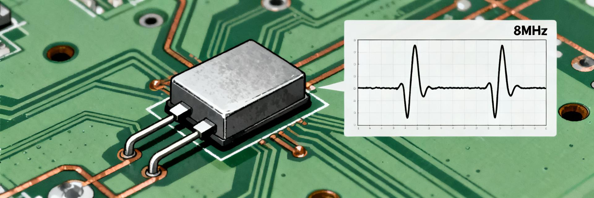
HCM498000000ABJT 8MHz Crystal: Complete Spec Report
Data-driven catalog listings and datasheets consistently list HCM498000000ABJT as an 8MHz crystal with 18 pF load capacitance, ±30 ppm initial tolerance and typical ESR near 100 Ω. These core electrical fingerprints make it a common selection for MCU clocking and simple timing functions.
1 — Product Overview & Key Specs
| Parameter | Value (Datasheet Range) | Note |
|---|---|---|
| Nominal Frequency | 8.000 MHz | Fundamental Mode |
| Frequency Tolerance | ±30 ppm | At 25°C baseline |
| Frequency Stability | ±50 ppm | Over −40°C to +85°C |
| Load Capacitance (CL) | 18 pF | Required for target freq |
| ESR (Typical) | ~100 Ω | Max limit varies by vendor |
| Package Style | HC-49US / SMD | Low profile surface mount |
2 — Electrical Characteristics & Data Analysis
Frequency Behavior
Initial ±30 ppm is the baseline; temperature and aging add error. Worst-case error calculation: Initial (±30) + Temp (±50) + Aging (±5) ≈ ±85 ppm. At 8 MHz, this equates to ±680 Hz deviation—acceptable for general MCU control but marginal for high-speed UART or precision RTC tasks.
ESR & Drive Level
The ~100 Ω ESR determines startup reliability. If the MCU oscillator input stage has low loop gain, high ESR can cause slow startup or failure to oscillate at low voltages. Engineers should ensure the oscillator’s negative resistance is at least 5x the crystal’s ESR.
3 — Validation & Measurement Procedures
Verification follows standard industrial protocols:
- Bench Measurement: Use an LCR meter for ESR and a high-impedance probe with a frequency counter for PPM offset.
- Thermal Stress: Cycle samples between -40°C and +85°C to verify the ±50 ppm stability curve.
- Load Pulling: Adjust external caps (C1, C2) to center the frequency at exactly 8.000000 MHz.
4 — PCB Design & Sourcing Recommendations
Layout impacts performance significantly. Keep traces between the crystal and MCU pins under 5mm. Use the formula C1 = C2 = 2 * (CL – Cstray). For this 18pF part, with a typical 3pF stray capacitance, 30pF or 33pF capacitors are the standard choice.
Summary
- HCM498000000ABJT is a robust 8MHz solution for industrial and commercial MCU timing.
- Requires 18pF load capacitance to achieve ±30ppm initial accuracy.
- Designers must account for the 100 Ω ESR in low-power oscillator circuits.
Frequently Asked Questions
How do I verify the frequency tolerance and stability of a crystal?
Use a calibrated frequency counter to measure at 25°C for initial tolerance and repeat measurements at −40°C and +85°C using a thermal chamber to determine temperature stability. Record ppm deviations and compare against datasheet limits.
What ESR limits should concern an MCU oscillator?
Typical ESR around 100 Ω requires the MCU inverter to provide sufficient loop gain; if the MCU oscillator stage is low-drive, parts with ESR >100 Ω may fail to start. Always verify the gain margin of your specific MCU.
How should incoming lots be qualified before assembly?
Perform lot verification by checking full part numbers and packaging, conducting spot frequency and ESR tests on a statistically meaningful sample (e.g., 30 units), and verifying RoHS and traceability documents.
What is the recommended capacitor selection for 18pF CL?
Follow the rule C1 ≈ C2 ≈ 2*(CL_spec − Cstray). For the HCM498000000ABJT with 18pF CL and 2pF stray capacitance, use 32pF or 33pF external capacitors to maintain the 8MHz center frequency.