


MBRA340T3G Datasheet Breakdown: Key Specs & Metrics
The MBRA340T3G is a low‑voltage, high‑frequency Schottky barrier rectifier with a repetitive peak reverse voltage of 40V, a nominal average forward current of 3A, and an ultra-low forward voltage drop. This breakdown focuses on the critical electrical and thermal metrics required for robust PCB integration.
1 — Device Overview & Application Fit
1.1 Device Class & Package ID
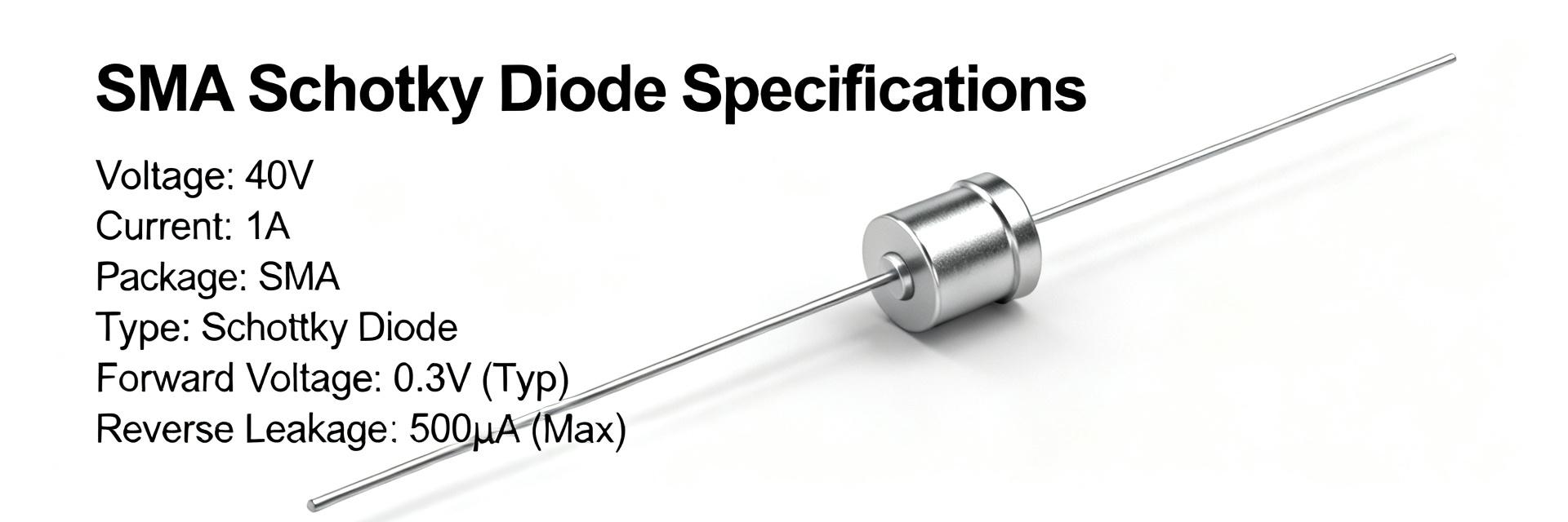
The device is a Schottky barrier rectifier housed in a standard SMA (DO-214AC) surface-mount package. For PCB designers, this represents a balance between high current density and a compact footprint, ideal for space-constrained power stages.
1.2 Primary Use Cases
Typical applications include low-voltage high-frequency inversion, freewheeling in DC-DC converters, and polarity protection. Its fast switching nature significantly reduces losses compared to standard silicon rectifiers.
2 — Electrical Specifications: Design Data
| Specification Parameter | Typical Datasheet Value |
|---|---|
| Peak Repetitive Reverse Voltage (V_RRM) | 40 V |
| Average Rectified Forward Current (I_O) | 3.0 A (@ T_L = 100°C) |
| Forward Voltage Drop (V_f) | ~0.45V @ 3A (Typical) |
| Non-Repetitive Peak Surge (I_FSM) | 80 A (8.3ms Half-Sine) |
| Reverse Leakage Current (I_R) | 0.2 mA @ 25°C / 20 mA @ 100°C |
3 — Thermal & Mechanical Architecture
3.1 Thermal Resistance & Derating
The RθJA (Junction-to-Ambient) is highly dependent on the mounting pad size. With standard soldering, expect ~60-80 °C/W. To maintain the 3A rating, thermal management must ensure the lead temperature (T_L) stays below 100°C.
4 — Real-Load Performance Metrics
Conduction loss is calculated as P_cond = V_f × I_f. At a full 3A load, the device dissipates roughly 1.35W. Since the SMA package is small, designers must utilize large copper planes on the cathode terminal to act as a heatsink, preventing thermal runaway caused by increased reverse leakage at high temperatures.
5 — Design Integration Checklist
- Voltage Margin: Ensure V_RRM is at least 20% higher than peak ringing voltages.
- Thermal Relief: Use minimum 50mm² copper area for optimized heat dissipation.
- Polarity: Verify the cathode band orientation in the pick-and-place file.
6 — Comparison Guidance
When substituting the MBRA340T3G, prioritize matching the V_f at 3A. Even a 0.1V increase in V_f can result in a 300mW increase in heat, which may exceed the thermal limits of an SMA footprint without redesigned cooling.
FAQ
What are the most important MBRA340T3G specs to check for rectifier use?
Check V_RRM for voltage margin, If(AV) and Vf at your operating current for conduction loss, RθJA and Tj(max) for thermal budgeting, and IFSM for surge handling. Also include leakage at max temperature when estimating standby loss.
How do I compute conduction loss from the datasheet specs?
Use Pdiss = Vf(at your If) × If. Choose Vf from the datasheet curve at the actual current (not just the typical point), then multiply by average current and duty cycle if used in a switching regulator.
What layout and assembly checks should I perform before placing an order?
Verify the recommended land pattern and thermal pad from the datasheet, confirm the reflow profile fits your process, and ensure the cathode marking is correctly identified in your CAD library.
Why is reverse leakage current (Ir) important for this device?
Schottky diodes like the MBRA340T3G have much higher leakage than standard diodes. This leakage increases exponentially with temperature, contributing to overall power loss and potential thermal instability in high-temperature environments.