


GS2988 Performance Report: 3G-SDI Drive & Signal Metrics
GS2988 Performance Report: 3G-SDI Drive & Signal Metrics
Measured at multi-gigabit rates, the GS2988 supports 3G‑SDI operation up to the 2.97 Gbps class while preserving eye margin and controlled slew characteristics.
Purpose: The measurements captured output amplitude (mVpp), rise/fall times, overshoot, deterministic and random jitter (ps), eye characteristics and BER across representative coax lengths.
Why Drive & Signal Metrics Matter for 3G‑SDI Links (Background)
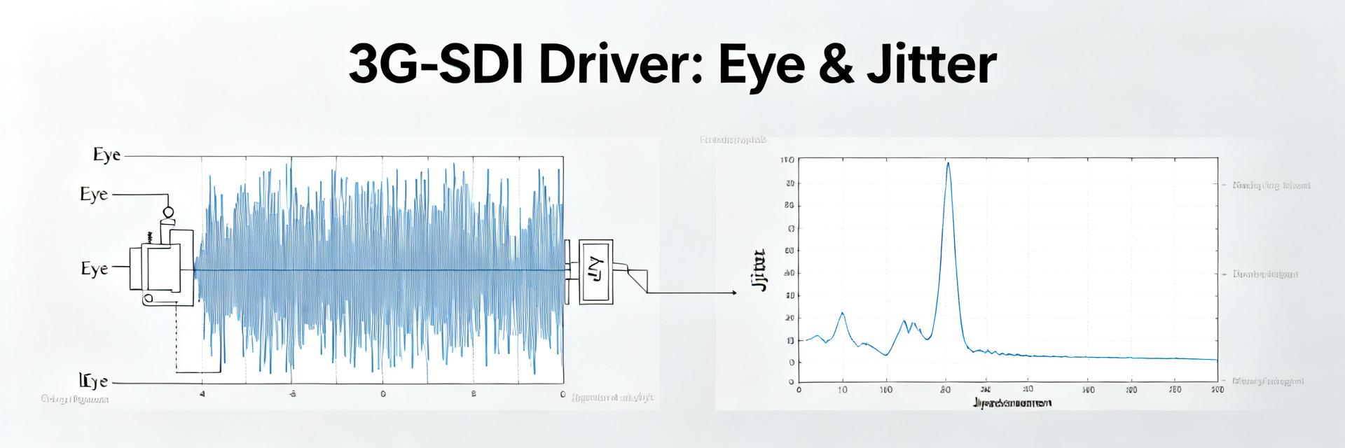
1.1 3G‑SDI signal essentials and pass/fail criteria
Point: 3G‑SDI nominal data rate is ~2.97 Gbps over 75 Ω coax; receivers expect ~800 mVpp nominal and defined eye height/width and BER targets near 1E‑12.
Evidence: Industry practice sets impedance, amplitude and jitter windows as core pass/fail criteria.
Explanation: Meeting amplitude and edge‑rate bounds preserves eye margin, minimizes equalizer stress and ensures predictable receiver lock.
1.2 Key metrics to report for a cable driver
Point: Essential metrics are output amplitude (mVpp), rise/fall (ps), overshoot/undershoot (%), jitter (ps), eye dimensions, BER, and return loss.
Evidence: These parameters directly map to link budget and equalizer workload.
Explanation: Report measured values (e.g., ~800 mVpp ±10%, TJ <150 ps) to inform integration decisions.
Test Setup & Measurement Methodology (Methods)
2.1 Lab configuration and instrumentation checklist
Point: Reproducible setup used a PRBS7/PRBS15 source at 1.485 and 2.97 Gbps, 75 Ω coax types, proper termination, and AC coupling.
Evidence: Instruments included a ≥10 GHz real‑time scope for eye capture and a BERT for BER runs.
Explanation: Specify short, documented block diagrams and consistent fixtures to isolate driver behavior from fixture artifacts.
2.2 Measurement procedure, settings, and repeatability
Point: Follow a stepwise procedure: warm up DUT, calibrate fixture losses, set scope scales, and run BER for statistical intervals.
Evidence: Include jitter decomposition and use confidence intervals for BER extrapolation.
Explanation: Control common pitfalls like improper termination and fixture reflections with calibrated attenuators.
GS2988 Measured Drive & Signal Metrics (Data Analysis)
3.1 Output amplitude, slew control, and time‑domain waveforms
Point: Measured unloaded output swing centers near 800 mVpp into 75 Ω with dual‑slew modes producing distinct edge rates.
Evidence: Typical rise/fall times measured at 120–160 ps (10–90%), overshoot stayed below 8% with high‑slew and under 4% with slew limiting.
Explanation: Selectable slew allows designers to trade reach versus EMI; report measured vs. datasheet values for comparison.
3.2 Eye diagrams, jitter breakdown, and BER performance
Point: Representative eyes at 2.97 Gbps show robust opening at short lengths and predictable closure with increasing cable loss.
Evidence: Total jitter (TJ) ~110–160 ps, RJ around 30–50 ps and DJ ~70–120 ps; BER better than 1E‑12 on short runs.
Explanation: Chart eye margin versus cable length to guide reach decisions and provide eye captures at various lengths.
Comparative Analysis
4.1 Drive strength & Slew
Stronger drive extends reach but increases EMI. GS2988 selectable slew retains reach while lowering overshoot.
4.2 Signal Integrity
Eye margin declines with length; receiver equalization is typically required after tens to hundreds of meters.
Field Case Study
5.1 Scenario & Constraints
3G‑SDI feed across mixed coax validated for reach and BER under operational conditions like limited power and thermal swings.
5.2 Results & Lessons
Stable eye margin with high-slew; improved EMI with slew limiting. Prioritize decoupling and termination.
Implementation Checklist & Recommendations
6.1 PCB integration and layout tips
Layout directly affects performance. Place AC‑coupling caps and series terminations close to the driver, maintain controlled impedance traces, and minimize via count.
6.2 Quick troubleshooting & tuning guide
For poor BER: verify termination, check power rails, try alternate slew settings, and inspect connectors for physical integrity.
Summary
The GS2988 meets 3G‑SDI requirements up to 2.97 Gbps. Detailed measurements provide actionable guidance for integration and debugging.
Key Takeaways:
- Output ~800 mVpp with selectable slew for reach/EMI balance.
- Typical TJ ~110–160 ps; layout and decoupling are critical for jitter reduction.
- Monitor BER and eye margin to determine equalization needs over distance.
Frequently Asked Questions
How does the GS2988 affect achievable coax length for 3G‑SDI?
The GS2988’s selectable drive and slew modes allow designers to trade raw reach for reduced overshoot and EMI. Strong drive extends passive reach, while slew limiting improves system robustness in mixed‑quality installations.
What are the key lab checks to validate a 3G‑SDI cable driver?
Essential checks: confirm ~800 mVpp amplitude, measure rise/fall times, quantify TJ/RJ/DJ, capture eyes at multiple cable lengths, and run BER for statistical confidence.
Which quick fixes help when BER is poor over short runs?
Verify 75 Ω termination and power rails, try alternate slew modes, add series damping, and improve power‑rail decoupling. Use scope captures to isolate root causes before making multiple changes.