


SH30553P12A2000 datasheet: Full specs, pinout & wiring
SH30553P12A2000 datasheet: Full specs, pinout & wiring
Key performance figures a technician needs up front: typical continuous power ~680 W, nominal torque ~1.2–1.25 N·m, maximum speed up to 9,000 RPM, three-phase AC supply spanning a broad 115–480 VAC range, multiturn encoder (128 P/R), and M23-style power and feedback connectors. This article decodes the SH30553P12A2000 datasheet into concise, actionable pinout maps, wiring steps, and tested installation tips so integrators can wire, mount, and troubleshoot the motor with confidence. It also provides a compact wiring checklist and quick spec reference for procurement and commissioning.
Safety Note: All guidance assumes verification against the unit-specific OEM datasheet and the installed drive manual before applying power; follow electrical safety rules, use appropriate PPE, and de-energize systems before connector work.
Product overview & intended applications
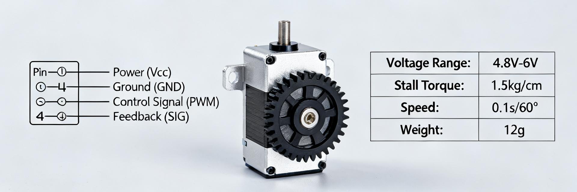
What the SH30553P12A2000 is and where it fits
Point: The SH30553P12A2000 is a 55 mm-frame high-speed servo motor family member designed for compact automation axes.
Evidence: It features a keyed shaft, three-stack rotor options and a multiturn encoder.
Explanation: That form factor and the ~680 W continuous power class make it suitable for high-speed servomechanisms, compact rotary tables, pick-and-place heads, and indexed automation where space and speed are primary constraints. Consult the SH30553P12A2000 datasheet for exact procurement attributes during ordering.
Full electrical & mechanical specifications
Electrical specs (must-have datapoints)
Point: Extract and verify core electrical numbers before specifying the drive. Evidence: Typical from datasheet values include ~680 W continuous, nominal torque ~1.2 N·m, max speed 9,000 RPM, and rated current values provided per model.
| Parameter | Typical value (from datasheet) |
|---|---|
| Continuous power | ~680 W (verify on original datasheet) |
| Nominal torque | ~1.2–1.25 N·m |
| Max speed | up to 9,000 RPM |
| Rated current (continuous) | refer to unit label (example ~1.7 A) |
| Supply | three-phase AC, 115–480 VAC range |
| Encoder | multiturn incremental, 128 P/R typical |
| IP rating | IP54 / IP65 options |
Mechanical & environmental specs
Point: Mechanical fit and environmental protection determine installation choices. Evidence: Typical 55 mm frame, keyed shaft diameter and standard flange mounting are used. Explanation: Capture shaft diameter and keyway dimensions, mounting flange bolt circle and length-to-face. Note enclosure/IP variant (IP54 or IP65), operating temperature range, natural convection cooling, mass, and weight.
Pinout summary & connector identification
Power connector (M23)
Point: Correct phase and earth pin mapping prevents drive faults. Evidence: M23-style power connectors commonly assign U/V/W to three main pins with a dedicated PE pin. Explanation: Map U/V/W to the drive phases, connect protective earth first. Typical: U=black/brown, V=white/blue, W=gray/black.
Feedback & encoder pinout
Point: Feedback wiring determines closed-loop accuracy. Evidence: Multiturn incremental encoders provide A/B/Z channels plus +V and GND. Explanation: Identify pins for A, B, Z, +V and GND. Use twisted-pair shielded cable. Reference SH30553P12A2000 pinout for documentation.
Step-by-step wiring & installation guide
Power wiring: step-by-step
Pre-check insulation, de-energize system, route cable with correct bend radius, secure strain relief, connect PE first, then connect U/V/W and torque fasteners to datasheet-specified torque. Record values on the installation sheet.
Feedback & signal wiring: step-by-step
Route encoder cable away from power runs, use shield grounded at one end (drive end), fit termination resistors for differential receivers, and confirm encoder counts and index presence before enabling closed-loop.
Performance validation & thermal considerations
Thermal limits: Read the thermal and duty-cycle charts for allowable ambient temperatures. During commissioning perform no-load speed checks and monitor winding temperature with a thermocouple.
Electrical protection: Fit recommended fuses or breakers, configure drive current limits below peak ratings for commissioning, and start with conservative velocity and torque loop gains.
Faults, troubleshooting & checklist
Typical wiring mistakes
Use a multimeter to verify phase continuity and earth. Check encoder A/B signals with an oscilloscope for clean differential square waves. Isolate power and feedback cables to diagnose EMI-related faults.
Final installation & commissioning checklist
- Confirm mechanical mounting and shaft coupling.
- Torque values recorded for all connectors.
- Correct phase and PE wiring verified via continuity.
- Encoder counts verified in drive software.
- Initial low-speed test run with load monitoring.
Summary
- SH30553P12A2000 datasheet decoded: capture continuous power, torque, and encoder resolution before procurement.
- Pinout and wiring: map U/V/W and PE on M23 connector; use shielded twisted pairs for encoder lines.
- Installation checklist: follow PE-first connection and apply conservative drive tuning for safe commissioning.
Frequently Asked Questions
How do I verify SH30553P12A2000 encoder counts during commissioning?
Use the drive’s encoder monitor or an oscilloscope to view A/B differential channels while slowly rotating the shaft. Confirm the expected P/R (e.g., 128 P/R) and index pulse.
What are the safest SH30553P12A2000 wiring tips for avoiding EMI-related faults?
Separate power and feedback cables, use shielded twisted-pair encoder cable with the shield grounded at the drive end only, and avoid parallel runs.
How should I approach motor overheating or thermal derating?
Start with conservative duty cycles and monitor winding temperature. Consult datasheet derating curves and implement thermal protection in the drive settings.