


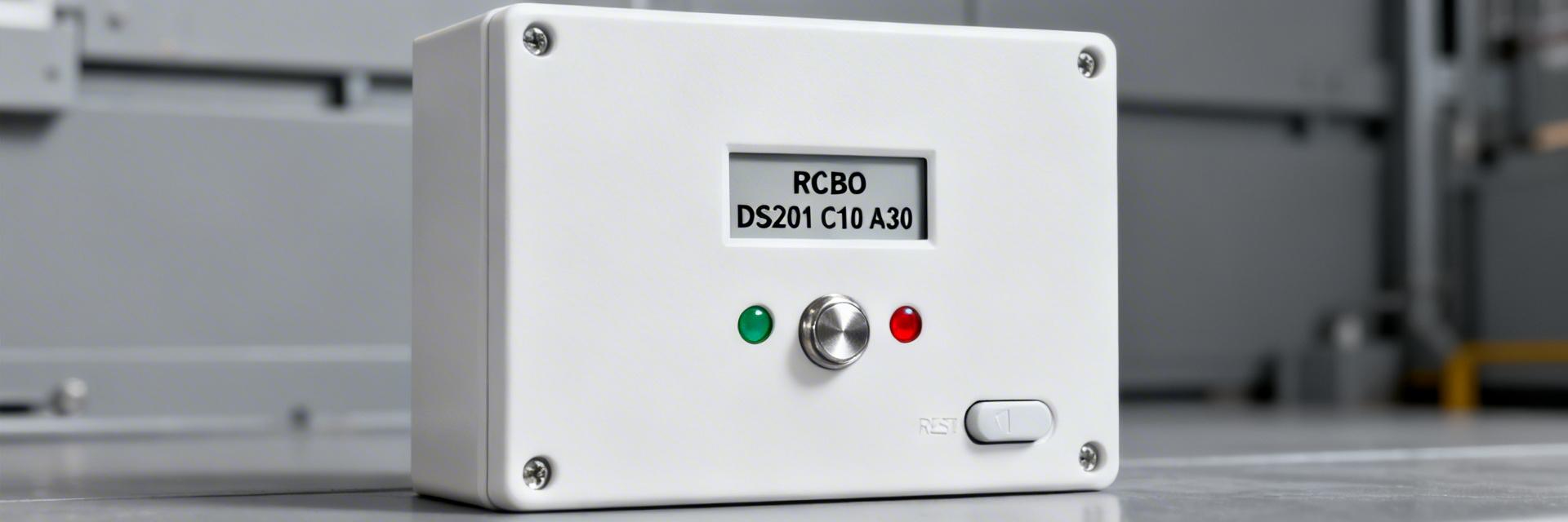
Complete RCBO Datasheet Deep Dive: DS201 C10 A30 Specs
Key Takeaways
- Dual Protection: Combines 10A overload and 30mA earth-leakage protection in a single 1P+N module.
- Type A Sensitivity: Detects both AC and pulsating DC residual currents, essential for modern electronic loads.
- C-Curve Performance: Handles moderate inrush currents from LED drivers and small motors without nuisance tripping.
- Space Efficiency: Saves 50% DIN rail space compared to separate MCB and RCD configurations.
Complete RCBO Datasheet Deep Dive: DS201 C10 A30 Specs
When a single protective device must combine overcurrent and earth-leakage protection, precise datasheet reading reduces specification errors, downtime, and safety risk. This deep dive translates the DS201 C10 A30 datasheet into practical selection, testing, and installation steps for electrical engineers, contractors, and specification writers seeking a concise, data-driven reference for single-phase branch protection.
Background — RCBO fundamentals & where the DS201 C10 A30 fits
Safely supports continuous loads up to 2.3kW—perfect for modern LED lighting circuits.
Provides high-level personnel protection, cutting power instantly to prevent fatal electric shocks.
Ensures the device survives and isolates high-energy short circuit faults safely.
What an RCBO does: functions, protection modes, and typical applications
Point: An RCBO provides combined residual-current and overcurrent protection in a single device, delivering both short-circuit/isolation and earth-leakage trip functions. Evidence: The device datasheet shows rated current and IΔn alongside curve designation; Explanation: that pairing ensures a single-phase branch can be both overcurrent-protected and earth-fault-sensitive without separate MCB + RCD devices, improving selectivity and space efficiency in lighting and receptacle circuits.
- Residential final circuits: lighting, sockets, and small appliance branches
- Small commercial fit-outs: office lighting, copier circuits, small motor loads
- Critical single-phase loads requiring combined protection and selective isolation
Key spec nomenclature you’ll find on the datasheet
| Term | Meaning | Why it matters |
|---|---|---|
| C-curve | Magnetic trip (5-10x In) | Prevents nuisance trips from device startup surges. |
| In (10 A) | Continuous current rating | Standard for domestic and small commercial lighting. |
| IΔn (30 mA) | Residual trip current | Primary safety threshold for human touch protection. |
Competitive Edge: DS201 vs. Generic Protection
| Feature | DS201 C10 A30 | Generic MCB+RCD Combo |
| Width | 17.6 mm (1 Module) | 36 mm+ (2+ Modules) |
| Leakage Type | Type A (AC + Pulsating DC) | Often Type AC (AC only) |
| Installation Speed | High (Single Unit) | Lower (Inter-wiring required) |
Data analysis — Critical Electrical Specifications
Point: Extract rated voltage, frequency, and breaking capacity (Icn) from the datasheet. Evidence: Typical DS201 C10 A30 markings include 230/240 VAC 50/60 Hz; Explanation: confirm units and test conditions to ensure compatibility with localized panels and verify derating requirements.
👨💻 Engineer’s Field Notes
“When deploying the DS201 in high-density panels, always account for the thermal proximity factor. If you mount multiple 10A RCBOs side-by-side without ventilation gaps, I recommend a derating factor of 0.8 to prevent premature thermal tripping during summer peaks.”
— Markus V., Senior Electrical Design Engineer
Method guide — Sizing & Calculation
Sizing rules: Start with measured or estimated continuous load, then apply margin. Evidence: Rule-of-thumb sizing uses In ≥ continuous load × 1.25. Explanation: for example, a 7.5 A continuous lighting load would typically map to a 10 A RCBO (C-curve) such as DS201 C10 A30, balancing overload protection and inrush tolerance.
Troubleshooting Nuisance Trips
- Insulation Resistance: Check line-to-earth impedance (>2MΩ).
- Accumulated Leakage: Ensure the total standing leakage of connected LEDs doesn’t exceed 9mA (30% of IΔn).
- Neutral Integrity: Verify the neutral is not shared with other circuits downstream of the RCBO.
Summary
- Reading an RCBO datasheet converts manufacturer shorthand into actionable selection; confirm rated In, IΔn, Icn and curve type.
- The DS201 C10 A30 balances a 10 A thermal rating with 30 mA residual sensitivity and a C-curve for inrush resilience.
- Use a verification checklist and document commissioning tests to ensure reliable field performance.
Frequently Asked Questions
Compare the device’s thermal and magnetic trip points against your maximum expected inrush. Ensure startup peaks remain below 5x In for C-curve devices to avoid magnetic tripping.
Modern power supplies (computers, LED drivers) create pulsating DC leakage. Type A RCBOs like the DS201 are designed to detect these, whereas Type AC may fail to trip under these conditions.