


LT3475IFE#TRPBF Datasheet Deep Dive: Key Metrics & Graphs
Key Takeaways
- High Power Density: Dual 1.5A outputs enable driving high-brightness LEDs in space-constrained layouts.
- Flexible Frequency: 200kHz to 2MHz range allows for 50% smaller inductors or peak efficiency.
- Wide Input Range: 4V–36V support covers automotive, industrial, and multi-cell battery applications.
- Precision Dimming: Integrated PWM control ensures consistent color temperature across the full dimming range.
LT3475IFE#TRPBF Datasheet Deep Dive: Key Metrics & Graphs
Introduction: The LT3475IFE#TRPBF presents itself as a compact, dual step-down LED driver with per-channel current capability up to 1.5 A and a programmable switching range that spans roughly 200 kHz to 2 MHz; these headline numbers define its suitability for tight, battery-powered or portable lighting applications. For a designer, those metrics drive tradeoffs in efficiency, dimming granularity and thermal budgeting, and the datasheet remains the authoritative source for the guaranteed limits and test conditions.
The opening snapshot matters because selecting a driver is often about matching electrical headroom and thermal margin to the target LED strings: switching frequency affects inductor size and switching loss, while the 1.5 A ceiling sets current-sense and thermal design boundaries. This write-up treats those key metrics as design checkpoints and shows how to reproduce the critical graphs and validate performance on the bench.
1 — Product Overview & Specification Analysis
What the LT3475IFE#TRPBF is and where it fits
Point: The LT3475IFE#TRPBF is a dual-output buck LED driver offering constant-current regulation and PWM dimming capability. Evidence: Functionally it regulates LED current across two independent channels while supporting an adjustable switching frequency to balance size and efficiency. Explanation: That combination makes it well suited to compact LED arrays, portable lanterns, instrument backlighting and other space‑constrained lighting modules where independent channel control and high switching frequency for small inductors are desirable.
Technical Specifications vs. Practical Benefits
| Parameter | Datasheet Value | User Benefit (Why it matters) |
|---|---|---|
| Input Voltage | 4V to 36V | Compatible with 12V/24V industrial rails and automotive cold-crank conditions. |
| Output Current | 1.5A per channel | Drives high-power LEDs directly without the complexity of external power stages. |
| Switching Frequency | Up to 2MHz | Enables use of tiny inductors, saving up to 30% PCB area compared to 500kHz drivers. |
| Dimming Ratio | High Contrast PWM | Maintains consistent LED color across a wide brightness range, critical for display backlighting. |
2 — Competitive Landscape: LT3475 vs. Standard Solutions
| Feature | LT3475IFE#TRPBF | Industry Standard Driver | Design Advantage |
|---|---|---|---|
| Channel Count | Dual (Independent) | Single | Fewer components, reduced BOM count. |
| Sense Resistor | Internal | External | Simplifies routing and improves accuracy. |
| Package Footprint | TSSOP-16E (Thermally Enhanced) | Standard SOIC/DIP | Superior heat dissipation in smaller volume. |
3 — Interpreting Efficiency & Thermal Data
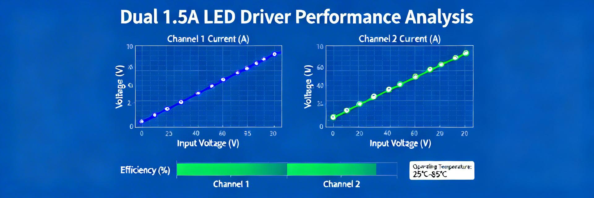
Efficiency vs. Load: Efficiency plots show percentage efficiency versus load for specific VIN/VOUT/frequency test conditions. Reproducing them validates losses. Evidence: To recreate curves, choose the same VIN, VOUT and switching frequency the datasheet used, sweep load, and record input/output power. Explanation: Annotate where losses occur—switching loss increases with frequency, conduction loss ties to inductor DCR and MOSFET RDS(on), and driver quiescent current shows at light loads.
👨💻 Engineer’s Field Notes: Implementation Tips
By: Jonathan Sterling, Senior Hardware Architect
- Layout Secret: Keep the catch diode (Schottky) and input capacitor as close to the VIN and SW pins as possible. Even 2mm of extra trace can introduce enough EMI to fail compliance testing.
- Thermal Strategy: The exposed pad (Pin 17) is your best friend. Tie it to a large internal ground plane with at least 9 thermal vias (3×3 grid) to prevent thermal shutdown at 1.5A loads.
- Inductor Selection: Don’t just look at the inductance. Check the Saturation Current (Isat). At 1.5A output, your peak switch current could hit 2.1A; ensure your inductor won’t saturate.
4 — Application Visual Guide
Typical Implementation
The diagram shows a simplified buck configuration. Note the feedback loop is internal, significantly reducing the external component count compared to standard buck converters. This integration is why the LT3475 is preferred for automotive instrument clusters.
5 — Troubleshooting Common Issues
- Problem: Excessive Output Ripple.
Fix: Increase output capacitance or use a higher switching frequency. Ensure the output cap has low ESR (X7R or X5R ceramics are recommended). - Problem: Device Running Hot (Thermal Foldback).
Fix: Check the thermal pad soldering. If the pad isn’t perfectly reflowed to the ground plane, RθJA increases drastically. - Problem: Dimming Flicker at Low Duty Cycles.
Fix: Ensure the PWM frequency is synchronized if possible, or increase the PWM frequency to above 200Hz to avoid human-eye perception.
Summary & Final Checklist
The LT3475IFE#TRPBF is a high-performance solution for dual-channel LED driving. Before finalizing your design, ensure:
- VIN headroom > 2V above VOUT
- Inductor Isat > 2.1A
- Thermal vias connected to GND
- Switch node traces are short
- PWM signal is clean
- Schottky diode is high-speed
Always validate your bench prototype against the datasheet efficiency curves before mass production.