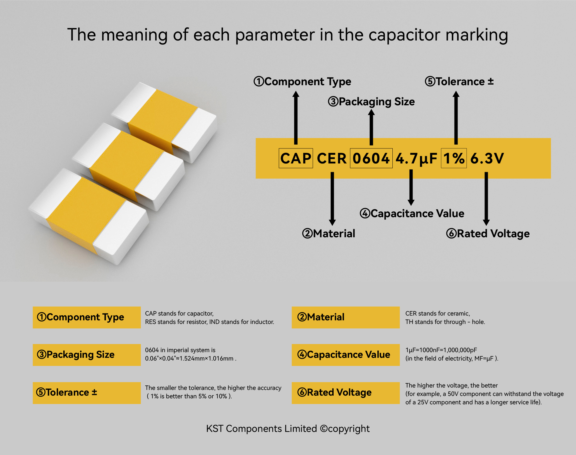
The meaning of each parameter in the capacitor marking
①Component Type
– “CAP” is a common abbreviation for “capacitor”, similar to “RES” for resistor and “IND” for inductor.
②Material
– Terms like “CER” (ceramic), “ALUM” (aluminum electrolytic), and “TANT” (tantalum) indicate the manufacturing material of the capacitor, which can narrow down the search scope.
– “TH” stands for through-hole capacitors (such as old-style disc ceramic capacitors or aluminum electrolytic capacitors), also known as “radial” or “axial” components.
③Packaging Size
– For example, “0805” is the dimension code for SMD (surface mount device) capacitors, determining the physical size (commonly used for ceramic or tantalum capacitors). Matching dimensions are required for replacement; otherwise, circuit board redesign may be needed. Other common dimension codes include 0201, 0402, and 0603.
④Capacitance Value
– Values like “4.7uF”, “1uF”, “1pF” are the core specifications of the capacitor. The units include pF (picofarad), nF (nanofarad), uF (microfarad, also written as μF), mF (millifarad, rare), and F (farad, for supercapacitors, etc.). Try to match this value as closely as possible; in some projects, a close value may be acceptable, but when in doubt, prioritize matching.
– Special note: In the power electronics field (such as motor capacitors), “MF” usually means microfarad (uF), not millifarad (mF) literally. This is a “pitfall” formed by industry historical habits, which needs attention when searching for related capacitors.
⑤Tolerance ±
– Numbers with “%” like “1%”, “5%”, “10%” indicate the tolerance, i.e., the range by which the actual capacitance value can deviate from the nominal value (default ±, e.g., ±10%). Smaller tolerances mean higher precision (1% is better than 5% or 10%). In special cases (e.g., old components), the tolerance values on the positive and negative sides may differ (e.g., +80/-20%). Generally, components with lower tolerance can replace those with higher tolerance, but the reverse requires consulting an engineer.
⑥Rated Voltage
– Numbers with “V” like “25V”, “50V”, “6.3V” are the rated voltages (working voltage WV), i.e., the maximum steady-state voltage the capacitor can withstand without damage. For some capacitors (such as film capacitors), the rated voltages for alternating current (VAC) and direct current (VDC) are different, which needs to match the application scenario. Higher voltage is better (e.g., a 50V component can withstand the voltage of a 25V component and has a longer lifespan). Do not replace a high-voltage component with a low-voltage one unless the circuit has special margin design.
By understanding these marking rules, even those without an electronics degree can find basic capacitor components on websites according to their needs.