


🚀 Key Takeaways
- Power Peak: Must support 2A bursts to prevent brownouts during TX.
- Global Connectivity: Quad-band GSM (850/900/1800/1900MHz) for worldwide 2G coverage.
- Ultra-Compact: SMT footprint reduces PCB area by ~30% compared to legacy modules.
- IO Flexibility: Integrated Bluetooth 3.0 and GPRS up to 85.6 kbps for versatile IoT.
SIM800C Datasheet Deep Dive: Key Specs & Pinout Guide
The SIM800C datasheet frames the module as a tiny, quad-band GSM/GPRS SMT solution that supports GPRS up to 85.6 kbps, voice, and SMS. This deep dive translates datasheet parameters into actionable guidance to help engineers evaluate electrical trade-offs and avoid common power or antenna pitfalls.
Transforming Specs into User Benefits
Prevents unexpected system resets during high-power network handshakes.
Reduces BOM footprint, allowing for smaller, sleeker wearable or industrial enclosures.
Enables local wireless configuration without opening the device casing.
Market Differentiation: SIM800C vs. Common Alternatives
| Feature | SIM800C (Standard) | SIM800L (Economy) | SIM7600 (4G Upgrade) |
|---|---|---|---|
| Network Generation | 2G (Quad-band) | 2G (Dual-band) | 4G LTE / 3G / 2G |
| Bluetooth | Yes (3.0) | No | Optional (4.0) |
| Peak Power Supply | 2.0A @ 4V | 2.0A @ 4V | ~0.8A - 2.0A |
| Cost Index | Medium-Low | Lowest | High |
Quick Overview: What the SIM800C is and Where it Fits
The SIM800C is a compact quad-band GSM/GPRS module in an SMT package intended for constrained IoT endpoints. It combines voice, SMS, and low-rate data in a small footprint, trading higher cellular throughput for size, cost, and low-power topology.
Key Technical Specifications
- RF Performance: GPRS multi-slot class 12/10. Max data rate: 85.6 kbps.
- Electrical: Voltage range 3.4V ~ 4.4V. Power-saving mode consumes
- Mechanical: 42-pin SMT pad layout. Dimensions: 17.6 * 15.7 * 2.3 mm.
"Expert Tip: Most newcomers fail to account for the voltage drop on the VBAT line during the 2A transmission burst. Even if your power supply says 4V, a high-ESR capacitor or thin traces can cause a drop to 3.2V, leading to a module crash. Always use a 100uF low-ESR tantalum capacitor combined with a 10uF ceramic capacitor right at the VBAT pin."
Method Guide: Pinout & Signal Descriptions
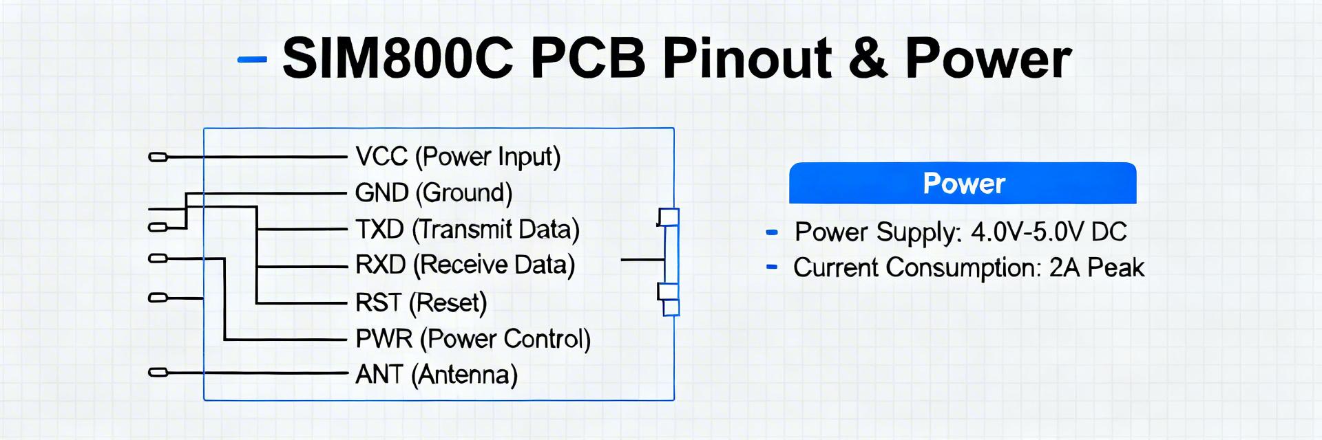
Mapping the 42 pins correctly is vital. The core groups include:
- VBAT: Power Input
- UART: TXD/RXD for AT Commands
- SIM: 1.8V/3V Interface
- RF_ANT: 50 Ohm Antenna Pad
- PWRKEY: Power On/Off Logic
- ADC: Analog Measurement
Typical Application: Remote Telemetry Node
Design logic: The MCU sends sensor data via UART; the SIM800C handles the GPRS stack and network negotiation.
Troubleshooting Checklist
- Cannot Register: Verify antenna SWR is
- Boot Loop: Measure VBAT with an oscilloscope to catch voltage dips below 3.4V.
- No UART Response: Check if the logic level is 2.8V (standard for SIM800C) and use level shifters for 5V MCUs.
Common Questions
Ensure a low-ESR bulk capacitor (100uF+) sized to handle 2A peaks, and verify regulator dropout during transient loads to avoid brownouts.
Match UART logic levels to VDD_IO (2.8V). Implement level shifters for 3.3V or 5V systems. Wire RTS/CTS for hardware flow control in high-data-rate scenarios.
Keep the antenna area free of copper, provide a solid ground plane with stitching vias, and place the matching network as close to the module as possible.