


DLPA3005DPFDR Datasheet Deep Dive: Key Specs & Pinout
As modern pico-projector and high-current LED modules push for higher integration and smaller BOMs, integrated PMIC plus LED driver ICs are appearing more often in reference designs. This article provides a focused, actionable walkthrough of the device datasheet, highlighting the most important electrical specifications, the full pinout and package notes, and practical design and test guidance for engineers working on compact illumination modules.
Quick Overview: what the DLPA3005DPFDR is and where it fits
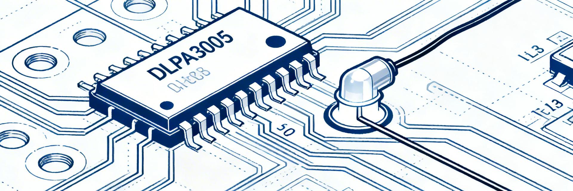
One-line functional summary and target applications
The part is an integrated PMIC with multi-rail power conversion and a high-current LED driver intended for compact projection and illumination modules. It combines buck/regulator stages with multiple LED sink channels, on-chip protections and digital control, making it attractive when PCB area and component count must be minimized in battery-powered or mains-fed designs.
High-level block diagram and feature checklist
A concise block diagram should show VIN rails feeding buck converters and LDOs, switching FETs, multiple LED current sinks, sensing/protection blocks, and a control interface. Key features to verify: input range and regulator outputs, per-channel LED current capability and accuracy, thermal/current limit, dimming interfaces, and any fault/monitoring registers required for system integration.
Key Electrical Specifications & Performance
Input and regulator rails
Extract VIN range, recommended operating voltage and absolute maximums from the datasheet, plus nominal regulator outputs and their max currents. Note typical regulator currents and any sequencing constraints for VIN, EN, or RESET pins. Where sequencing is required, enumerate the order and timing windows to avoid brown-out or inrush issues during power-up and hot-plug events.
LED driver specs & Efficiency
Pull the LED sink ranges, number of channels and accuracy figures, dimming methods (PWM and analog), switching frequency, and maximum per-channel voltage. Summarize thermal and current limit behavior and how switching frequency, input voltage and load affect end-to-end efficiency.
Critical Performance Metrics (Typical)
Pinout, Package and Critical Pin Functions
Package notes and thermal considerations
Discuss the package thermal path and recommended solder pad footprint. Specify thermal via count and diameter guidance for a robust thermal path under the exposed pad, recommend a copper pour on internal layers tied to the pad, and describe standoff/keepout and component clearance needed for reliable reflow and mechanical mounting in constrained enclosures.
Design & Implementation Guidelines
Typical application schematic and BOM
Map critical externals: input bulk and ceramic decoupling, switching inductors (saturation and DCR targets), output capacitors with ESR guidance, current-sense resistor tolerance and power rating, snubbers or damping networks and recommended ferrite beads for input filtering. Call out selection criteria and typical value ranges tied to regulator currents and expected LED loads.
Layout, decoupling and EMI/thermal
Prioritize short high-current loops for switch nodes, place decoupling capacitors as close as possible to VIN and regulator pins, and route LED returns with wide traces. Use a thermal via grid under the exposed pad, plan internal copper pours for heat spreading, and include input filtering and snubbers to control switching node ringing.
Testing, Debugging and Application Notes
Lab test checklist
- • Validate rails with no load.
- • Confirm enable/sequencing behavior.
- • Measure each LED channel current.
- • Run thermal soak tests at rated ambient.
Common issues & Troubleshooting
Typical failures include no output due to sequencing or EN pin misconfiguration, flicker from insufficient decoupling or unstable compensation, thermal shutdown from inadequate thermal vias, and current inaccuracy from sense resistor tolerance or layout errors. Prioritize debugging by checking VIN, ENABLE, and sense resistor continuity.
Summary
Engineers should use the datasheet to locate absolute-max ratings, regulator output tables and the full pinout, then prioritize pins that affect thermal and control behavior when creating PCB layouts. Focus early validation on power sequencing, LED accuracy and thermal performance to avoid late-stage redesigns. Refer to the official datasheet for absolute limits and timing diagrams, and validate the pinout in prototype hardware.
Key Takeaways
- ✓ The datasheet centralizes VIN ranges, regulator outputs and per-channel LED sink limits; verify these numbers against system supply margins before selecting external components.
- ✓ Pinout organization is critical: treat power inputs, the exposed thermal pad and sense/feedback pins with priority in layout.
- ✓ Design choices for inductors, sense resistors and output capacitors strongly impact LED accuracy, loop stability and EMI.