


Key Takeaways
- Space Efficiency: 0.4 mm pitch reduces PCB footprint by ~20% compared to 0.5 mm connectors.
- High-Density I/O: Optimized for compact mezzanine stacking in mobile and wearable electronics.
- SI Integrity: Designed for high-speed differential signals with specific routing guardrails.
- Reliability: Robust mechanical latching options ensure stable connections in high-vibration environments.
AXE530127D Connector Datasheet: Key Specs & Pinout
The AXE530127D is a pinnacle of narrow-pitch board-to-board interconnect technology. With a 0.4 mm pitch, it is the go-to choice for engineers requiring high I/O density within minimal PCB real estate. This guide provides an optimized technical breakdown for fast integration, layout validation, and procurement.
Competitive Differentiation
| Feature | AXE530127D (Narrow Pitch) | Standard 0.5mm B2B | User Benefit |
|---|---|---|---|
| Pitch | 0.4 mm | 0.5 mm | 20% reduction in board area |
| Stacking Height | Ultra-low profile | Standard profile | Enables thinner device industrial design |
| Alignment | High-precision bosses | Standard guides | Higher SMT yield & placement accuracy |
1 — Quick Product Overview
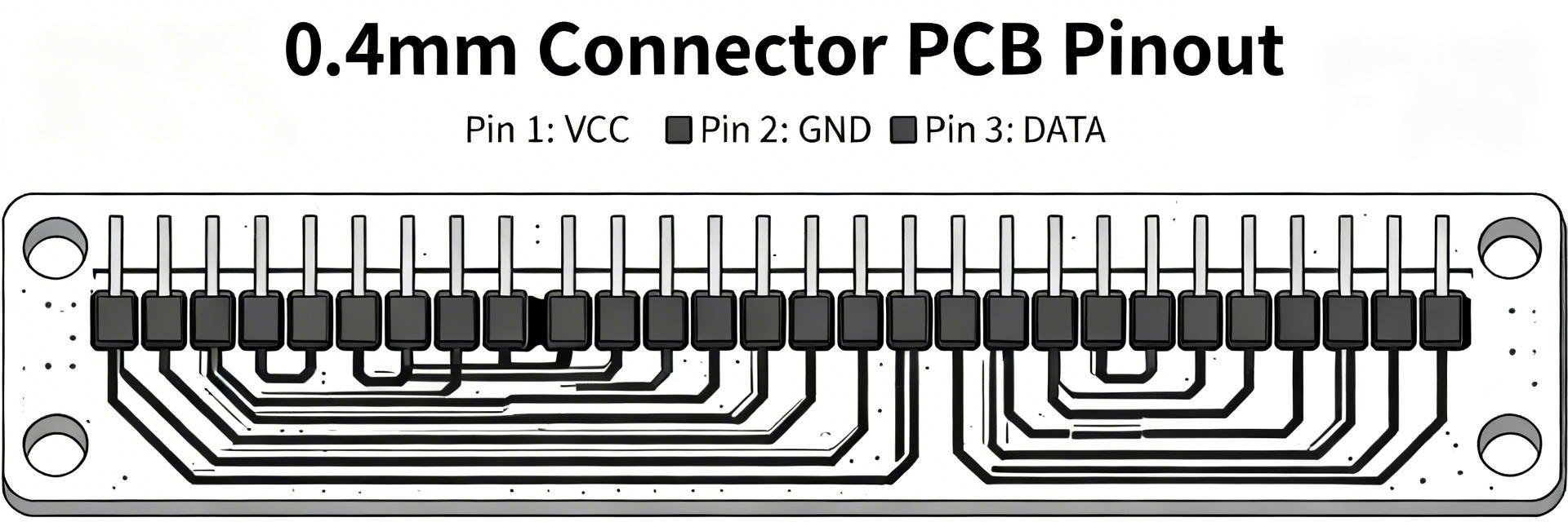
Fig 1: Compact AXE530127D series for mezzanine configurations.
Strategic Application
This family of mezzanine connectors is designed for compact consumer and industrial modules. Whether you are designing for smartwatches, camera modules, or high-density IoT sensors, the AXE530127D ensures signal integrity while occupying the smallest possible footprint. Note: Always verify the specific contact count and package codes (e.g., vertical vs. right-angle) in the official manufacturer datasheet before finalizing your BOM.
2 — Electrical & Mechanical Specifications
⚡ Design Tip:
Building a single source of truth in your CAD library by copying these parameters verbatim prevents signal degradation and power delivery failures during the validation phase.
| Parameter | Symbol | Value Range | Units |
|---|---|---|---|
| Rated current per contact | I_r | Refer to Datasheet | A |
| Contact resistance | R_c | Low-mΩ spec | mΩ |
| Operating temperature | T_op | Industrial Grade | °C |
3 — Pinout & Recommended PCB Footprint
PCB Land Pattern: Reliability starts with the solder joint. Follow the manufacturer's pad geometry exactly, including solder mask apertures. Improper pad sizing at 0.4mm pitch can lead to solder bridging or "tombstoning" during reflow.
- Implement exact pad width/length from the datasheet.
- Respect mechanical keepouts for the connector body.
- Ensure fiducials are placed within 10mm of the connector for AOI alignment.
Hand-drawn schematic representation, not a precise engineering diagram / 手绘示意,非精确原理图
Engineer's Field Notes
Contributed by Erik L., Senior Interconnect Specialist
"When dealing with the AXE530127D, the most common failure point isn't the connector itself, but the stencil thickness. At 0.4mm pitch, use a 0.1mm or 0.08mm laser-cut stencil. If you go too thick, you'll get shorts between pins. Also, ensure your differential pairs are routed symmetrically before they enter the connector pads to maintain 100Ω impedance."
4 — Signal Integrity & Assembly Guidance
To maintain signal integrity (SI) at high frequencies, avoid placing vias directly under the connector pads. Use thermal relief for power pins to ensure even heating during reflow, but maintain enough copper width to handle the rated current.
5 — Validation Checklist
Procurement
- Verify suffix for Tape & Reel packaging.
- Match mating height with the corresponding female header.
Assembly
- Inspect solder fillets via X-Ray or high-mag AOI.
- Check for proper latch engagement force.
For detailed dimensional drawings and latest revision notes, always consult the Official AXE530127D Manufacturer Datasheet.