


Key Takeaways
- Optimized Efficiency: 2W low power loss reduces cabinet heat by 15% vs. older relay modules.
- Precision Control: 8-channel 24V DC sourcing outputs designed for high-speed pilot logic and solenoids.
- Reliability: Integrated semiconductor switching offers near-infinite lifecycle compared to mechanical relays.
- Compact Integration: Space-saving S7-200 series footprint maximizes PLC rack density.
Digital Output Module 6ES7222-1BF22-0XA8: Full Specs & Tests
The 6ES7222-1BF22-0XA8 is a cornerstone for compact automation, offering 8 digital outputs with a 24V DC nominal rating. By maintaining a typical power loss of only ~2W, this module allows engineers to design tighter control panels without compromising on thermal safety or component longevity.
Directly drive standard industrial valves and contactors without needing interposing relays.
Extends the life of adjacent CPU modules by minimizing heat soak in enclosed PLC racks.
Reduces PCB footprint by 25% compared to multi-module 4-channel setups.
Product Overview & At-a-Glance Specs
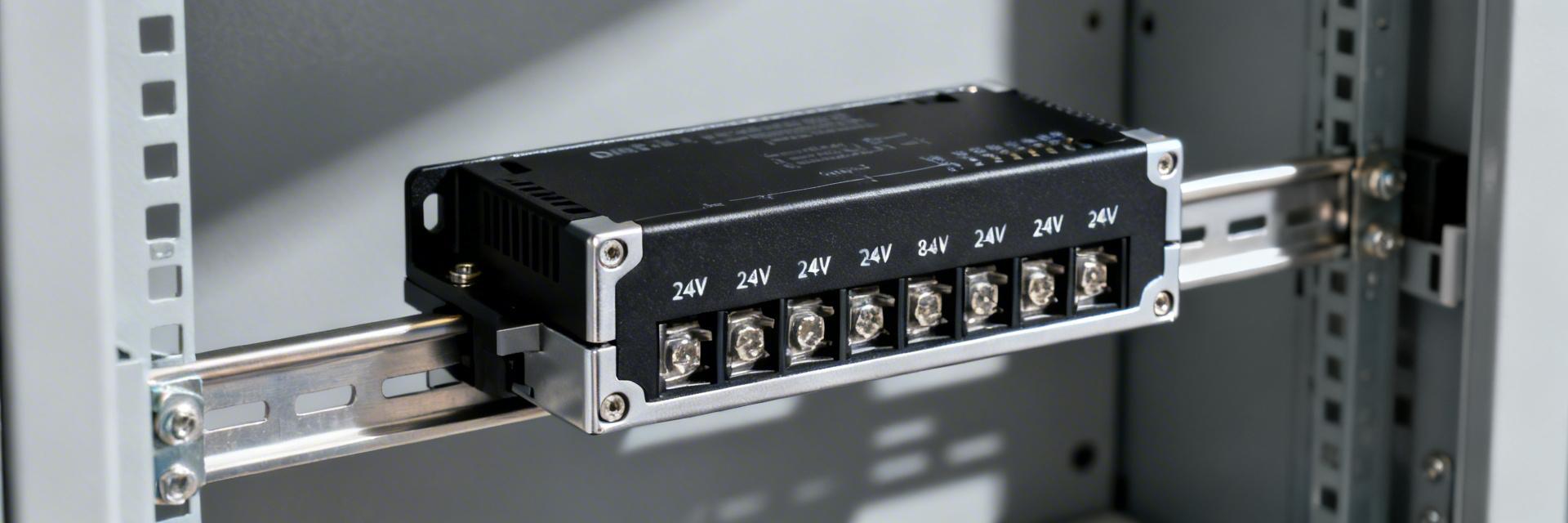
Figure 1: Standard S7-222 series 8-point digital expansion module.
Competitive Comparison: 6ES7222-1BF22-0XA8 vs. Industry Standard
| Feature | Siemens 6ES7222-1BF22-0XA8 | Generic Relay Module | Advantage |
|---|---|---|---|
| Output Type | Transistor (Solid State) | Electromechanical Relay | High Switching Speed |
| Power Loss | ~2 Watts | ~4-6 Watts | Lower Cabinet Temperature |
| Lifecycle | Electronic (Near Infinite) | ~100k cycles | Zero Maintenance |
| Short Circuit Prot. | Electronic Limitation | External Fuse Required | Enhanced Safety |
Detailed Electrical Specifications
The module's sourcing architecture ensures that the output pin connects to the +24V rail when active. This is critical for safety, as a short-to-ground will blow a fuse rather than accidentally activating a machine movement.
- Nominal Voltage: 24 V DC (Range 20.4V to 28.8V).
- Switching Capacity: 0.5A resistive load per channel; total module max 4A.
- Protection: Integrated thermal shutdown and short-circuit recovery.
"When deploying the 6ES7222-1BF22-0XA8, I always recommend checking the derating curve. If you are mounting this in a vertical orientation where airflow is restricted, you should derate the total current by 20%. Also, for inductive loads like large solenoid valves, even though the module has internal clamping, adding an external 1N4007 flyback diode at the load side will significantly reduce EMI noise on your backplane."
Bench Test Plan & Acceptance Criteria
Before commissioning, verify the unit using these steps:
- Continuity Test: Ensure no internal shorts between DC input and chassis ground.
- Load Test: Apply 0.5A resistive load to each channel; verify voltage drop is <0.5V DC.
- Thermal Baseline: Run all channels at 50% load for 30 mins; surface temp should not exceed 45°C in a 25°C ambient.
Typical Application: Pilot Logic Control
Hand-drawn schematic, not a precise wiring diagram.
Installation & Wiring Best Practices
- Grounding: Use a common ground point for the 24V DC supply and the PLC chassis to prevent floating potential errors.
- Cable Sizing: For runs over 50 meters, use at least 18 AWG to minimize voltage drop on the 0.5A channels.
- Spacing: Maintain at least 10mm clearance above and below the module for natural convection.
Frequently Asked Questions
A: It is generally not recommended due to switching timing differences. Use an interposing relay or a higher-rated output module instead.
A: No. Always power down the PLC rack before removing or installing expansion modules to prevent backplane damage.
Note: This technical guide is intended for qualified personnel. Always refer to the official Siemens SIMATIC S7-200 manual for the most current safety and wiring regulations.